Learning through wired models
I built a smart traffic-light system and a separate transit elevated-bus model. Both were working electronic models, wired by hand with logic gates controlling their operating sequences.
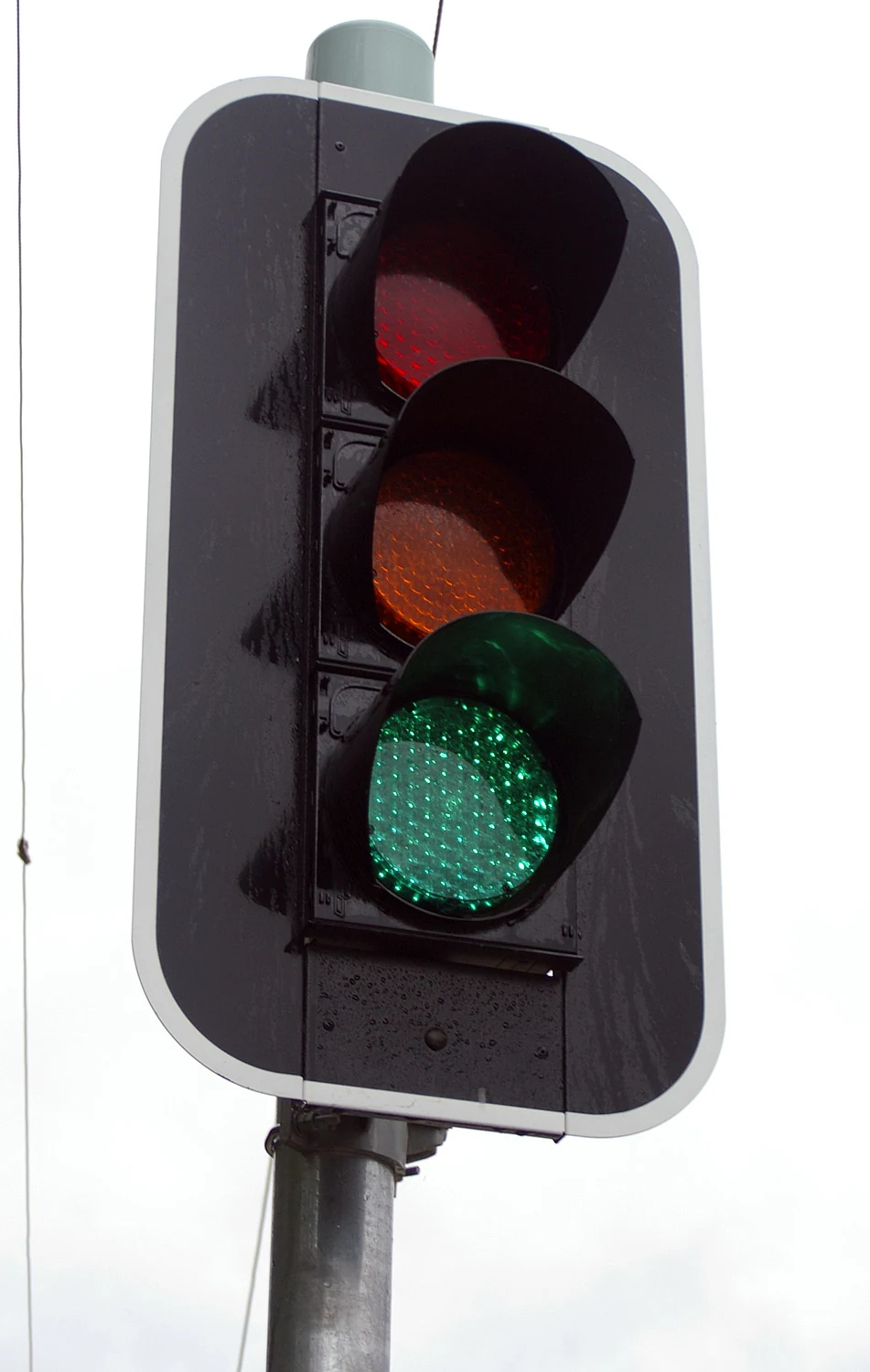
For the traffic-light system, I connected the signal lights into a repeatable junction sequence. For the elevated-bus model, I built a separate control circuit, then traced faults in the connections and logic until the sequence behaved consistently.
Thinking about the sequence
A simple way to express one signal-control requirement is:
If gᴺˢ and gᴱᵂ are binary indicators for conflicting green signals, this condition says they should not be active together. It illustrates the logic question in a model junction, rather than establishing compliance with real traffic-control standards.
These were early model-scale builds, not deployed transport systems. They gave me practice turning an operating sequence into a wired circuit and following faults when it did not behave as expected.